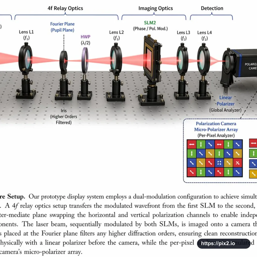
Create a square 1:1 scientific optical setup diagram on an optical breadboard table with a regular grid of mounting holes. Show a red laser beam passing horizontally through all optical components from left to right. Add top grouping brackets labeled [First Component Group], 4f Relay Optics, Imaging Optics, and Detection. Arrange the components left to right: a black rectangular Laser labeled [Laser Wavelength], SLM1 as a black square device on a post labeled Phase / Pol. Mod., Lens L1 labeled f1 in a black ring mount, an Iris at the Fourier Plane / Pupil Plane with higher orders filtered, an HWP half-wave plate labeled lambda/2 with a purple-tinted optic, Lens L2 labeled f1, SLM2 labeled Phase / Pol. Mod., Lens L3 labeled f2, Lens L4 labeled f2, a Linear Polarizer labeled Global Analyzer, and a blue-black Polarization Camera. Use a clean technical paper-figure style with realistic optical mounts, precise labels, thin leader lines, consistent perspective, and clear beam alignment. Add a bottom-right dashed-border inset titled [Inset Title] (Per-Pixel Analyzer), showing a 4x4 grid of colored squares with white directional arrows and a four-item legend: red right arrow 0 degrees H, green up arrow 90 degrees V, blue diagonal arrow 45 degrees D, and yellow diagonal arrow 135 degrees A. Add a bottom caption area: Fig. 5, [Setup Title], followed by [Figure Caption]. Keep the figure polished, readable, and suitable for a scientific publication diagram. Avoid real company logos, extra watermarks, clipped components, unreadable labels, impossible optical alignment, random extra lenses, incorrect beam path, distorted mounts, cropped caption, and low-resolution artifacts.

 1:1 ・ 4K